
English version machine-translated from the Vietnamese original — under review.
A summary of the requirements for testing and evaluating air leakage through the casing and the damper/valve of variable air volume (VAV) terminal units, and the permissible limits:
I. Overview of VAV and Test Standards
- Variable air volume (VAV) terminal units are a type of air terminal unit or terminal unit.
- The AHRI Performance Certification Program (AHRI 880) applies to VAV terminal units, requiring testing by independent third-party laboratories and compliance with ISO/IEC 17065:2012.
- ASHRAE 130:2016 provides test methods for rating different types of terminal units, including specific tests for valve/damper leakage, casing leakage and dynamic leakage. ASHRAE standards are voluntary unless mandated by a regulatory authority.
- BS EN 1751:1998 (British Standard) specifies aerodynamic testing of valves and dampers in ventilation systems. This standard uses ISO 5221 for airflow measurement.
- The SMACNA HVAC Air Duct Leakage Test Manual (ANSI/SMACNA Third Edition – 2005, ANSI/SMACNA 016-2012) provides duct test procedures for compliance with air leakage limits and emphasises the importance of understanding leakage from ducts, equipment (such as VAV air flow control boxes) and fittings. SMACNA does not recommend routine testing if appropriate methods are used, and visual inspection may be sufficient.
II. Leakage Test and Evaluation Procedures
The documents set out specific test procedures for casing leakage, damper/valve leakage and dynamic leakage:
1. Casing Leakage Test
- Purpose: To measure the amount of air leaking from the inside to the outside of the terminal unit. For parallel flow terminal units, leakage through the backdraft damper may be considered part of the casing leakage.
Per ASHRAE 130 (2008 & 2016):
- Test setup: The terminal unit is installed as shown in Figure 5 (2008) or Figure 6 (for supply air) and Figure 7 (for return/exhaust) (2016). Other installation arrangements may be used if described in detail in the test report.
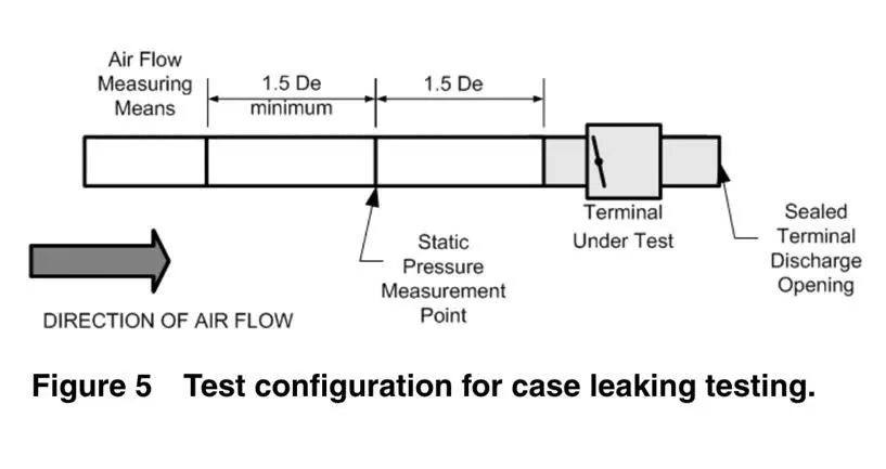
- Procedure: The airflow measuring apparatus is connected to a straight duct section at the primary air inlet. The primary damper/valve shall be fully open, and all other outlets and inlets shall be sealed. The inlet static pressure is measured. The supply airflow is increased until the desired static pressure is reached. Airflow and static pressure measurements are taken after equilibrium is reached.
- Reporting: Leakage is reported as "x cfm (L/s) at y in. (Pa) static pressure". A sample casing leakage calculation is provided for a 12-inch (300 mm) single duct terminal unit.
Per BS EN 1751:1998:
- Test setup: As in Figure 2a) or 2b). The outlet of the damper/valve casing is sealed, and the damper/valve is set to the open position.
- Procedure: The casing is held at the maximum recommended pressure for 60 seconds before the leakage measurement begins.
- Reporting: The report includes the classification (Annex C).
2. Damper/Valve Leakage Test
- Purpose: To measure the leakage of the control valve or the leakage through the primary air damper in the closed (shut-off) position. This test applies to single duct, dual duct, series, parallel-flow fan-powered and mechanically regulated terminal units.
Per ASHRAE 130 (2008 & 2016):
- Test setup: The unit is installed as shown in Figure 2 (2008) or Figure 8 (2016). A supply air duct is connected to the inlet of the closed damper/valve, with all other openings in the terminal unit open.
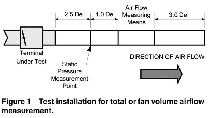
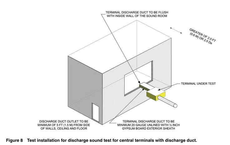
- Procedure: The supply air pressure is raised to the desired inlet static pressure. The damper/valve is then driven open and back to the closed position by its actuator. After the damper/valve has closed, the supply air pressure is adjusted to maintain the inlet static pressure within ±5% of the desired value after equilibrium.
- Reporting: The airflow rate is recorded as "primary air damper/valve leakage expressed as x cfm (L/s) at y in. (Pa) inlet static pressure". The air density (z lbm/ft³ [kg/m³]) is also included.
Per BS EN 1751:1998:
- Reporting: The damper/valve leakage airflow rate is reported as a function of the test pressure differential in the closed position, including the classification (Annex C).
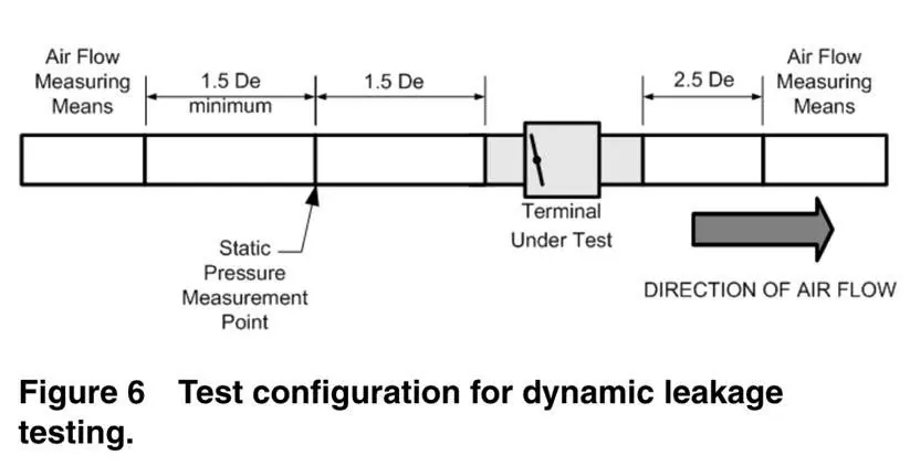
3. Dynamic Leakage Test (Applies only to Parallel-Flow Fan-Powered Terminal Units):
- Purpose: To determine the leakage through the casing and the backdraft damper when the primary air system is operating and the terminal unit fan is not running.
Per ASHRAE 130 (2016):
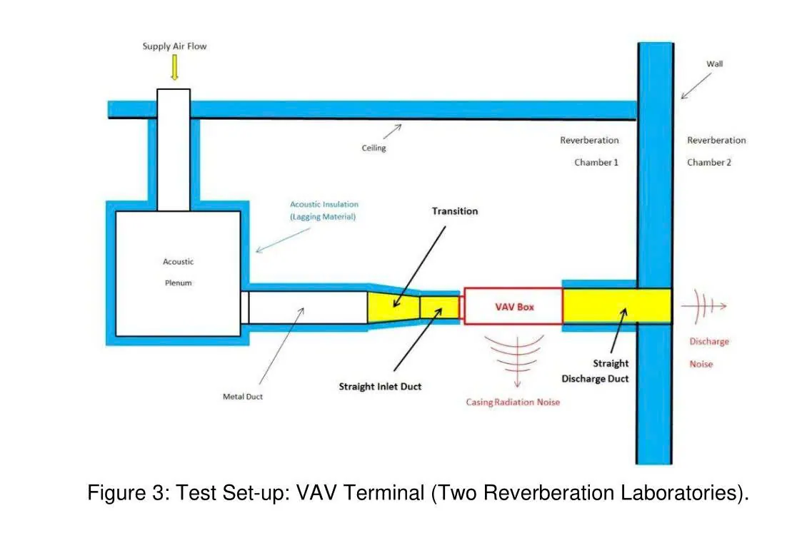
- Test setup: The terminal unit is installed as shown in Figure 3. The entire setup, except for the terminal unit, shall be sealed.
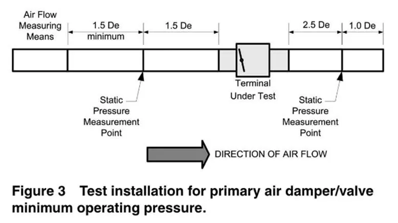
- Calculation: Dynamic leakage (Qleak) is the difference between the terminal unit inlet airflow (Qin) and the terminal unit outlet airflow (Qout) (Qleak = Qin - Qout).
- Reporting: Reported as "x cfm (L/s)" at the specified conditions: air density, terminal unit size, terminal unit airflow, inlet static pressure and outlet static pressure.
III. Permissible Leakage Limits and Classifications
Different standards provide different leakage limits and classifications:
1. Per SMACNA (HVAC Air Duct Leakage Test Manual):
- Leakage Class (CL): A constant that defines the leakage level based on the construction method.
- Leakage Rate (F): Expressed in cfm/100 ft² of duct surface area and calculated by the formula F = CL * P^0.65, where P is the static pressure in inches water gauge.
- Recommended leakage Classes (Table 5-1):
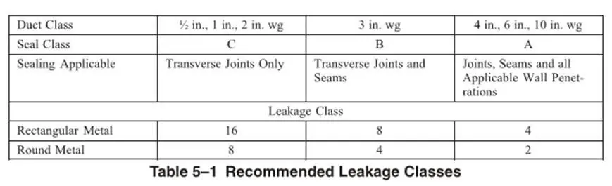
For rectangular metal duct:
- Leakage Class C (Transverse joints only): Class 16 (for 0.5 and 1 in. wg pressure).
- Leakage Class B (Transverse joints and seams): Class 8 (for 2 and 3 in. wg pressure).
- Leakage Class A (Joints, seams and all wall penetrations): Class 4 (for 4, 6 and 10 in. wg pressure).
For round metal duct: Generally tighter.
- Leakage Class C: Class 8.
- Leakage Class B: Class 4.
- Leakage Class A: Class 2.
Leakage as a percentage of airflow (Appendix A): Provides the rated cfm per ft² for different leakage classes and static pressures. For example, for leakage class 8:
- At 0.5 in. wg, 2.5 cfm/100ft² is allowed.
- At 1 in. wg, 4.0 cfm/100ft² is allowed.
- At 10 in. wg, 9.8 cfm/100ft² is allowed.
- Note: Section B.1 of SMACNA states that evaluating leakage by the percentage (%) method is not recommended as a complete evaluation of system performance, but may be useful for energy saving analysis.
Designers must account for leakage in equipment such as VAV/flow control boxes independently of duct leakage.
2. Per ASHRAE Fundamentals Handbook 2001 (Table 9):
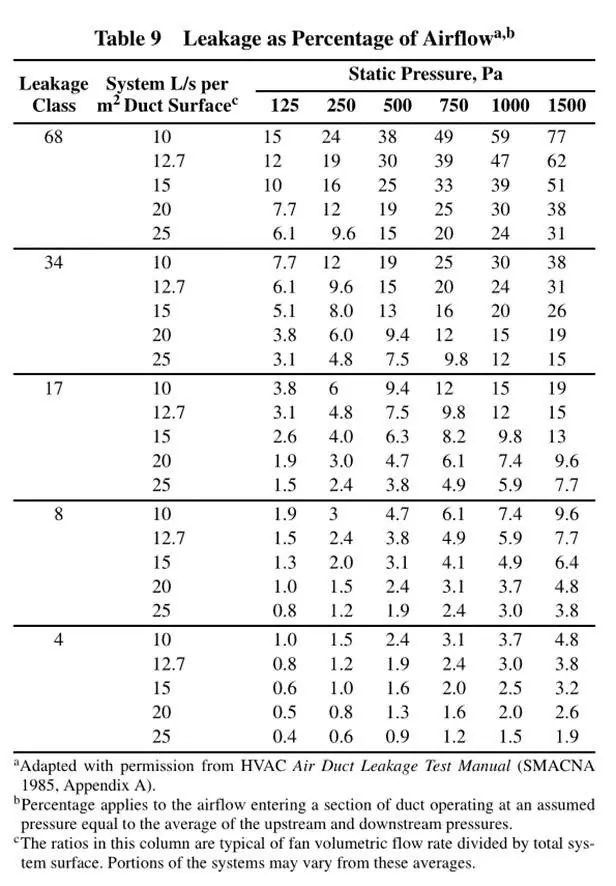
- Provides "Leakage as a percentage of airflow" in L/s per m² of duct surface for different Leakage Classes (8, 17, 34, 68) and static pressures (125 Pa to 1500 Pa). This table is adapted from SMACNA 1985.
- For example, Leakage Class 8 at a static pressure of 1000 Pa corresponds to 9.6 L/s per m² of duct surface.
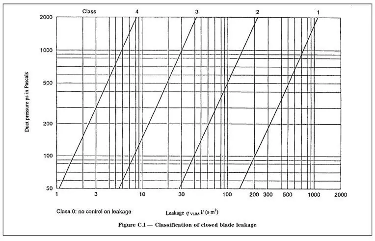
3. Per BS EN 1751:1998 (Annex C):
- Closed Blade Leakage (Figure C.1): Allowable maximum qvLBA (l·s⁻¹·m⁻²) as a function of duct static pressure (ps in Pa) for classes 1, 2, 3 and 4.
- Class 1 is the tightest, Class 4 is the least tight. For example, at 500 Pa, Class 1 allows approximately 1 l/s/m², while Class 4 allows approximately 20 l/s/m².
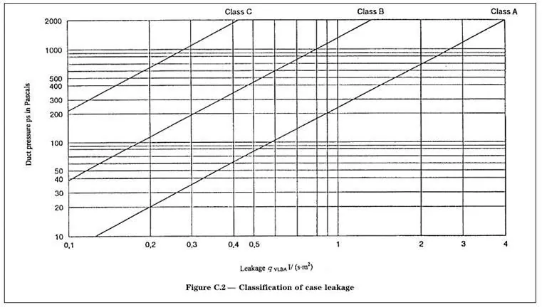
- Case Leakage (Figure C.2): Allowable maximum qvLCA (l·s⁻¹·m⁻²) as a function of duct static pressure (ps in Pa) for classes A, B and C.
- Class A is the tightest, Class C is the least tight. For example, at 500 Pa, Class A allows approximately 0.2 l/s/m², Class B approximately 1 l/s/m², and Class C approximately 5 l/s/m².
IV. Key Concepts and Notes
- Leakage is an important aspect of HVAC system performance, affecting energy efficiency.
- Different standards provide different leakage methods and classifications, reflecting differences in focus (e.g. product certification versus ductwork installation).
- SMACNA distinguishes between leakage from ductwork and leakage from equipment (such as VAV units), emphasising that designers should account for both separately.
- The concept of "leakage class" quantifies the airtightness of the duct construction, with lower numbers indicating less leakage.
- The "loss coefficient" (j or C) is a dimensionless fluid resistance coefficient used to evaluate the aerodynamic performance of components such as dampers and valves; it is distinct from leakage itself, but relates to pressure loss.
- Testing is not always necessary if appropriate construction and sealing methods are followed; visual inspection is often sufficient.
- There is a difference between static leakage (damper closed, unit off) and dynamic leakage (unit operating).
V. Conclusion:
Picture your HVAC system as a complex network of pipes carrying air. VAV casing leakage is like checking whether there are any cracks or holes in the pipe walls that allow air to escape before reaching its destination. VAV damper leakage, on the other hand, is like checking whether the control damper (blade) inside the pipe closes completely to stop the airflow from passing through when it is set to close. The permissible limits and leakage classes are set like quality control standards. They indicate the maximum acceptable level of air "loss" for different types of ducts and dampers, ensuring that the system operates efficiently without wasting too much energy. An efficient system is like a pipe with no cracks and a tightly closed damper, ensuring that all the airflow goes where it should.
Compiled and edited by the Research and Development (R&D) department of NSCA