
English version machine-translated from the Vietnamese original — under review.
HVAC VAV System Design – Basis and Applicable Standards
Introduction to VAV systems
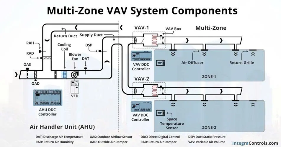
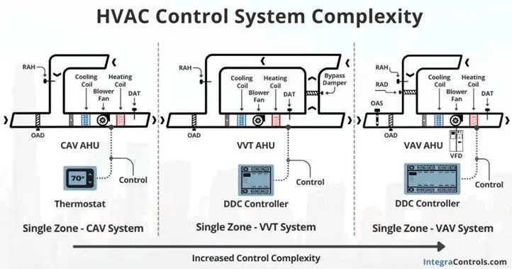
A VAV (Variable Air Volume) system is an air-conditioning system that varies the supply airflow according to the load of each area. Instead of delivering a constant airflow as a CAV system does, VAV adjusts the supply airflow to each zone through VAV boxes (airflow control dampers) to maintain the desired temperature. This saves energy (reducing fan power at low load) and increases flexibility in controlling the temperature of each area. When designing a VAV system, the engineer needs to determine the cooling load/heating demand of each room, select the appropriate VAV box size (with reheat or without heating), and determine a suitable duct static pressure and AHU/FCU supply air temperature so that the system operates stably.
A key benefit of VAV is the ability to maintain temperature and ventilation precisely according to the needs of each area, while still ensuring air quality and thermal comfort. Modern VAV systems are usually controlled by DDC (Direct Digital Control) connected to the BMS, enabling optimized control strategies that reduce energy consumption while still meeting the comfort standard (ASHRAE 55) and the air quality standard (ASHRAE 62.1). However, the greater complexity of VAV design demands strict compliance with standards and codes throughout design, construction and operation.
Applicable design standards and codes
When designing a VAV system, multiple industry standards and local codes must be referenced together to ensure the system meets technical, safety and performance requirements. Below are the key standards and their main relevant content:
ASHRAE Guideline 36-2021 (High-Performance Sequences of Operation for HVAC Systems)
ASHRAE Guideline 36-2021 provides standard control algorithms (sequences of operation) for HVAC systems to optimize performance. It is ASHRAE's first effort to standardize high-performance VAV control solutions in buildings. Guideline 36 sets out advanced sequences for common HVAC systems, designed to maximize energy efficiency and performance while still meeting ASHRAE's thermal comfort and ventilation standards, ensuring control stability and integrating fault detection (AFDD)[1]. With Guideline 36, control system manufacturers have developed ready-made program libraries that comply with the guideline, shortening programming time and reducing errors during BMS implementation[2].
For multi-zone VAV systems, Guideline 36-2021 specifically recommends the following control strategies to improve performance:
- Demand-based AHU static pressure adjustment: Apply the “trim & respond” method – i.e. automatically lower the duct static pressure setpoint until the most remote VAV box is almost fully open, then hold that level. This ensures the fan supplies only enough pressure to satisfy the most critical zone, avoiding excess pressure that wastes electricity[3]. (Note: since 1999, ASHRAE 90.1 has required VAV systems with DDC to provide static pressure reset based on the zone control dampers in order to save energy[4]).
- Dual-Max algorithm for VAV reheat: For VAV boxes with a reheat coil, Guideline 36 recommends the “dual maximum” strategy. This algorithm sets two airflow limits: maximum airflow in cooling and maximum airflow in heating (usually lower than the cooling level). When the room switches to heating mode, the VAV box first reduces airflow to the minimum required (usually equal to the required fresh airflow) and only then opens the hot water valve. If the heat is still insufficient, the VAV box then gradually increases airflow up to the second maximum (heating max). This control approach minimizes reheat energy and avoids simultaneous heating and overcooling[3]. Research shows that the dual-max strategy significantly reduces fan energy and heating energy compared with traditional VAV logic, because it avoids continuously holding a high minimum airflow that overcools the space and must then be offset by reheat[5][6].
- Integrated fault monitoring and automatic adjustment: Guideline 36 also covers the implementation of automated fault detection and diagnostics (AFDD) algorithms for AHUs and VAV boxes (e.g. an alarm when a VAV damper is fully open but the temperature setpoint is not reached, indicating insufficient airflow or a sensor fault). This helps the system operate reliably and supports proactive maintenance[3].
Thanks to this guidance, VAV boxes and AHUs that comply with Guideline 36 can operate optimally and in a coordinated way. Design engineers should refer to ASHRAE G36 to develop the control sequence description for the BMS, ensuring the VAV system achieves high efficiency right from the programming stage and is easy to operate and test.
ASHRAE Standard 62.1 (Ventilation for Acceptable Indoor Air Quality)
ASHRAE 62.1 specifies minimum ventilation rates to ensure acceptable indoor air quality. When designing VAV, the engineer must calculate the fresh airflow for each space according to the formulas and criteria of 62.1 (based on floor area and number of occupants). The VAV system must ensure that each zone always receives at least the minimum fresh air, even when airflow drops at low load. This is usually achieved through the VAV min value (the minimum airflow setpoint of the VAV box), set equal to or higher than the required fresh airflow.
In addition, Standard 62.1 also addresses air distribution effectiveness. For example, with ceiling supply systems, to avoid air stratification during heating, ASHRAE 62.1 requires that the heating air temperature from ceiling supply outlets be no more than 15°F (8.3°C) above the room temperature[7]. This requirement (together with the 20°F limit of ASHRAE 90.1[7]) leads to limiting the maximum supply air temperature to around 85-90°F (29-32°C) during heating, to ensure the warm air mixes sufficiently, maintain ventilation effectiveness and avoid “short-circuiting” (warm air rising to the ceiling and going straight back to the return)[7]. Combining these requirements, the engineer must both ensure sufficient fresh air and avoid supplying overly hot air at low airflow, which reduces effectiveness.
Furthermore, ASHRAE 62.1 encourages demand-controlled ventilation (DCV) for spaces with variable occupancy (such as meeting rooms and auditoriums). Using CO₂ sensors or schedules, the VAV system can increase/decrease fresh air to match occupancy and save energy while keeping the CO₂ concentration at an acceptable level (satisfying 62.1)[8]. DCV integration must also comply with the requirements of ASHRAE 90.1 (which allows fresh air to be reduced when occupancy falls) without violating the minimum levels of 62.1. In practice, LEED requires compliance with both 62.1 and 90.1, so the VAV design must be fine-tuned to avoid conflicts between ventilation and energy-saving requirements[9][10] (e.g. bypass reheat solutions for dehumidification that do not violate 90.1's prohibition on excessive reheat, etc.).
In summary, Standard 62.1 ensures that the VAV system supplies enough clean air to the occupants. The design must configure VAV minimum flow = max(required fresh airflow, technical limit of the box). If a very low minimum airflow strategy is used to save energy, it must be carefully checked that this airflow is not lower than the fresh air requirement and still ensures even air diffusion.
ASHRAE Standard 90.1 (Energy Standard for Buildings)
ASHRAE 90.1 sets minimum energy efficiency requirements for HVAC systems. For VAV system design, the important provisions of 90.1 include:
- Minimum limit for VAV reheat: To reduce energy wasted on reheating, 90.1 limits the minimum airflow of VAV boxes with reheat to no more than 30% of the maximum airflow (or no lower than the required fresh air level)[11]. In other words, VAV min ≤ 0.3 * VAV max (unless the required fresh air is higher than that). This provision aims to reduce the amount of surplus air that must be reheated when the cooling load drops. For perimeter zones with high heating loads, if 30% of the maximum airflow is still not enough for heating, 90.1 suggests alternatives such as fan-powered VAV boxes or supplementary independent heating instead of raising VAV min too high[11].
- Fan and static pressure control: 90.1 requires supply fans above 5 hp (3.7 kW) to have variable frequency drives or variable speed control to adjust airflow as the load changes. In particular, for VAV systems using DDC at the zone level, demand-based static pressure reset is mandatory[4]. That is, the BMS must automatically lower the fan pressure setpoint as the VAV dampers close down, to avoid the fan running at excess pressure and wasting electricity. This is the same “trim & respond” logic described in Guideline 36. Similarly, the AHU supply air temperature should be reset upward when the overall system cooling load decreases (to reduce reheat demand in the branches). 90.1 encourages supply air temperature reset for multi-zone systems when conditions allow[12].
- Fan, motor and equipment efficiency: Standard 90.1 sets limits on fan power per unit of airflow (W/CFM) for the entire duct system. The design must optimize duct pressure losses (the resistance of equipment, filters, air outlets, VAV boxes…) so that the total fan power does not exceed this limit. In addition, the minimum efficiencies of chillers, boilers, DX coils, motors… must also meet the values in 90.1. In Vietnam, QCVN 09:2017 references minimum COP requirements for air conditioners/chillers similar to the tables in 90.1[13].
- Limiting simultaneous heating and cooling: 90.1 has provisions prohibiting or restricting systems that both cool and heat the same area, with certain exceptions. For VAV reheat, the standard requires a deadband between the cooling and heating modes of each zone to avoid unnecessary reheat. In addition, the zones on the same system should be controlled so as to minimize cases where some zones must heat while other zones are cooling for extended periods (separate systems for interior and perimeter areas, or a heat recovery system, may be considered).
Overall, ASHRAE 90.1 steers VAV design toward maximum energy savings by limiting surplus air supply and heating. The engineer must strike a balance between meeting ventilation & load needs (per 62.1) and complying with energy limits (90.1). This is why intelligent control strategies such as dual-max and pressure/temperature reset are needed, along with consideration of system options (e.g. fan-powered VAV for perimeter rooms), to satisfy both standards[14][10]. Note that LEED requires minimum compliance with 90.1-2010 (or the corresponding version) as an energy prerequisite[15], so a VAV design aiming for green certification must certainly meet this standard as well.
ASHRAE Standard 55 (Thermal Environmental Conditions for Human Occupancy)
ASHRAE 55 specifies indoor thermal environmental conditions to ensure thermal comfort for the majority of occupants. The standard considers a combination of factors – air temperature, relative humidity, air speed and thermal radiation – together with personal factors (activity level – met, clothing – clo) to determine the acceptable comfort zone[16].
For HVAC design, ASHRAE 55 requires the system to maintain temperature, humidity and air speed within a range in which ≥80% of occupants feel comfortable. Specifically, designs typically aim to keep the temperature at about 22-26°C and RH at 40-60% in the occupied zone. The VAV system must modulate finely enough to avoid excessive room temperature swings or excessively high air speeds on occupants that cause a biting chill. The layout of VAV air outlets must avoid blowing directly on occupants and causing discomfort (local discomfort), while ensuring temperature uniformity in the room (avoiding large differences vertically and over time).
ASHRAE 55 also includes provisions on occupant control (e.g. in office spaces, there should be a means for occupants to partly adjust the temperature or local fans). In the context of LEED and other green certifications, a design that satisfies ASHRAE 55 is mandatory, and bonus points are available for providing comfort control tools for each area (such as easy-to-adjust thermostats, sun shades…).
In summary, Standard 55 reminds VAV designers that, beyond energy efficiency, the system must meet human comfort criteria. Cooling/heating load calculations should use design points that satisfy the thermal comfort zone (with PMV/PPD meeting requirements). At the same time, when programming VAV controls, mode changes and airflow changes must be smooth, preventing room temperature from fluctuating beyond comfort limits.
Local standards and other codes
In addition to the ASHRAE standards, when designing in Vietnam it is necessary to comply with the national standards and codes related to HVAC:
- TCVN 5687:2010 – Ventilation – Air conditioning – Design standards: This is the Vietnamese standard that covers a great deal of the design content for ventilation and air-conditioning systems in residential, public and industrial buildings. TCVN 5687 covers everything from indoor climate design parameters and ventilation, fresh air supply and ventilation arrangement requirements to requirements for dust filtration, exhaust, emergency ventilation, plant rooms, equipment installation, ductwork and smoke protection[17][18]. When designing VAV for a project in Vietnam, it must be checked whether the project owner/local requirements mandate TCVN 5687. For example, TCVN 5687 specifies the maximum air velocity in occupied areas and the maximum noise level, how to determine the fresh airflow per person (which may differ from ASHRAE 62.1), etc. It must therefore be ensured that there is no conflict between a design to ASHRAE and the requirements of TCVN (TCVN 5687:2010 usually has many similarities with ASHRAE but also differences due to Vietnamese conditions).
- QCVN 09:2017/BXD – National technical regulation on energy efficiency buildings: This regulation is mandatory for new buildings within its scope in Vietnam. For HVAC, QCVN 09 requires compliance with ventilation rates per QCXDVN 05:2008 (or an equivalent standard)[19], and includes provisions such as fans > 0.56 kW must have automatic controls to switch them off when not needed (except for continuous operation)[20]. This is similar to ASHRAE 90.1's requirement for variable frequency drives, but at a more basic level. In addition, QCVN 09:2017 sets duct insulation values, minimum efficiencies for cooling equipment, and requirements for compliance with the energy code in operation (e.g. not setting temperatures too low, which wastes energy…). A new VAV system design needs a design statement verifying compliance with the whole of QCVN 09 (as this is a mandatory regulation for building acceptance).
- IMC (International Mechanical Code) or IFC (International Fire Code) if the project applies international standards: the IMC provides provisions on equipment installation, safe ventilation, fresh air intake clearances, exhaust, fire damper requirements, smoke detectors in HVAC systems… The VAV design must comply with these requirements where required. For example: under IMC/NFPA, AHU systems > 2000 CFM must have a smoke detector in the return air duct to shut down the fan when fire is detected; fire dampers must be installed where ductwork passes through fire-rated walls; flexible ducts connecting VAV boxes must not exceed the permitted length; etc. These provisions are usually also reflected in TCVN 5687 and Vietnamese fire safety standards, so the engineer needs to cross-check them to produce a compliant design.
In summary, compliance with local standards is mandatory. The project brief must establish which set of standards takes priority (e.g. the project owner requires full compliance with ASHRAE & IFC, or TCVN/QCVN must be followed). In many cases, the design will combine both: using ASHRAE parameters and methods while still ensuring the minimum levels under TCVN/QCVN so as not to violate the law. Cross-referencing between standards should be made clear in the project's Design Criteria.
Duct design and installation standards (SMACNA, DW/144, etc.)
A VAV system includes a ductwork network distributing variable airflow, so the design and installation of ductwork and air outlets must follow industry standards for strength, leakage and pressure loss:
- SMACNA Standards: The standards of the Sheet Metal and Air Conditioning Contractors’ National Association (USA) are regarded as the “guiding reference” for the design & fabrication of duct systems. SMACNA provides detailed guidance on duct construction (sheet thickness, stiffening ribs and reinforcement, hanger spacing...), duct pressure classes (low/medium/high pressure), and joining and sealing methods (flange types, corner pieces, silicone sealant, leakage standards)[21][22]. Compliance with SMACNA helps ensure durable, airtight and safe ductwork and consistent quality across the whole project[23][24]. In the design documents, engineers often note “Ductwork fabrication & installation to SMACNA HVAC Duct Construction Standards, design pressure X inch WG” so that the installation contractor follows the standard correctly. SMACNA also provides guidance on duct system design (HVAC Duct System Design) to optimize pressure loss and achieve even air distribution, as well as standards for airflow measurement and balancing (TAB) of ductwork after installation.
- DW/144 (HVCA / B&ES): This is the British standard for ductwork manufacture and installation, issued by BESA and internationally recognized as equivalent to SMACNA[25]. Many projects in Vietnam (especially those with British/Singaporean consultants) require DW/144. This standard also classifies ductwork by pressure and specifies sheet thickness and flanges (usually designated Class A/B/C, corresponding to low/medium/high). The new edition of DW/144 expands its content on hangers and supports, fire dampers, fire-resisting ductwork, external ductwork, acoustically lined ductwork, insulation materials... to keep pace with European standards[26]. Essentially, compliance with either DW/144 or SMACNA aims to ensure ductwork quality (airtightness, durability and a service life of > 20 years). Design engineers should clearly state which standard is used in the drawings and specifications so that all parties involved apply it consistently.
- Other standards: Besides the two main standards above, others include Eurovent 2/2, JIS for sheet metal ductwork, or TCVN 5687 (which has a chapter on ductwork) as mentioned. If the project requires it, all general MEP installation standards should be listed, such as: IEC for electrical control systems, NFPA for fire protection integration (detectors, dampers), SMACNA HVAC Sound and Vibration (to control noise and vibration in the VAV system)...
In summary, a good VAV design does not only calculate airflows and equipment; it must also clearly specify the technical requirements for fabrication and installation of ductwork, air outlets, insulation and ancillary equipment according to reputable standards. This ensures that during construction the contractor has a basis for correct execution, and that at acceptance there are criteria to check against (e.g. what percentage of leakage SMACNA allows in duct leakage testing).
Green building standards (LEED, LOTUS, Green Mark, etc.)
Many projects today aim for green building certifications such as LEED (USA), LOTUS (Vietnam) and Green Mark (Singapore). HVAC VAV system design needs to consider the requirements of these rating systems so they can be integrated from the outset:
- LEED (Leadership in Energy and Environmental Design): The USGBC rating system. For HVAC, LEED requires strict compliance with ASHRAE 62.1 and 90.1 as prerequisites[15]. In addition, a project can earn points by exceeding the required performance level (e.g. saving more than 10% energy compared with the 90.1 baseline earns Optimize Energy Performance points). Applying high-efficiency VAV (with intelligent controls and reduced airflow at low load) will help increase points in the energy category. LEED also requires Commissioning (see the section below) as a mandatory requirement – meaning the VAV system must be operationally tested by a third party to verify design performance. Other related credits include Enhanced Commissioning, Enhanced Refrigerant Management (related to chiller/VRF), Thermal Comfort (ensuring ASHRAE 55 conditions – usually already covered if the design complies), and Indoor Air Quality Plan & Assessment (requiring a flush-out before handover or measurement of air quality parameters, for which the VAV ventilation system must operate correctly to supply sufficient airflow). In summary, a VAV design aiming for LEED should target high energy efficiency (exceeding 90.1) and good control of comfort and IAQ, while preparing for the commissioning and measurement work that follows.
- LOTUS: The green certification system of the Vietnam Green Building Council (VGBC), first issued in 2010[27]. LOTUS has many categories similar to LEED but adapted to Vietnam. For HVAC, LOTUS also requires compliance with QCVN 09:2017 (the energy code) and encourages outstanding performance. An efficient VAV system will help the building earn points in the categories of Energy (HVAC system efficiency, intelligent controls, limiting HCFCs…), Indoor Environment (thermal comfort, good ventilation, low noise) and Construction/Operation Management (commissioning plan, operator training). Because LOTUS is still relatively flexible, designers should consult the current LOTUS versions (NC, BI0, etc.) to ensure that equipment selections (e.g. chiller efficiency, whether or not to use VAV) suit the criteria.
- Green Mark: The standard of Singapore's Building and Construction Authority (BCA). Green Mark places strong emphasis on energy efficiency – with quantitative criteria such as the total cooling system efficiency (kW/RT) and fan efficiency per m³/s that a project must achieve to be certified[28]. VAV design can help meet these criteria by reducing fan load, but it also requires an optimized control system. Green Mark is also concerned with air quality and the thermal environment: it requires CO₂ sensors in densely occupied rooms and high-efficiency filters (MERV/Ashrae 52.2) to maintain IAQ. In addition, like LEED, Green Mark requires commissioning and measurement & verification of performance after the building is in operation. If the project targets Green Mark, the design engineer needs to work with the certification specialist to ensure the VAV system satisfies the criteria for electricity savings (through energy modeling), intelligent controls (BMS monitoring, scheduling, fault alarms) and user comfort.
Overall, green certifications do not introduce new design formulas; instead they consolidate requirements from ASHRAE, local codes and best practice and set higher targets. An advanced VAV system designed to Guideline 36, complying with 62.1 and 90.1, and fully provided with measurement and testing facilities and efficient operation, will help the project easily earn points in many categories of LEED, LOTUS and Green Mark.
Commissioning, testing & balancing (Cx & TAB)
A design is only successful when the actual system operates as intended. The commissioning (Cx) and testing, adjusting, balancing (TAB) phases are therefore especially important for VAV systems:
- Building Commissioning (Cx): A systematic quality assurance process to verify that all systems and equipment are installed, operated and maintained in accordance with the Owner's Project Requirements (OPR) and the established design criteria[29]. For HVAC VAV systems, commissioning includes checking the equipment setup (VAV boxes, sensors, valves, actuators), test-running the control sequences programmed in the BMS, and readjusting them if requirements are not met. ASHRAE Standard 202-2018 and Guideline 0-2019 provide detailed guidance for this process, covering the pre-design phase (defining the OPR, Cx planning), the design phase (reviewing the design against the OPR, including Cx requirements in the documents), through to construction, start-up, acceptance and operation[30][31]. In the design, the engineer should specify the scope of Commissioning (e.g. “The HVAC system and BMS shall be commissioned by a third party in accordance with ASHRAE Guideline 0 and Standard 202”), and prepare the documentation requirements (as-built drawings, O&M manuals, operator training) for Cx. The benefit of commissioning for VAV systems is ensuring the system actually achieves its design performance, with setup or programming errors detected early (e.g. sensors in the wrong location, non-optimized control algorithms) and corrected before handover. Many project owners and green certifications (LEED mandates Fundamental Cx and awards points for Enhanced Cx) require Cx, so it is no longer an option but an item that must be included in the project plan.
- Testing, Adjusting, Balancing (TAB): The work of measuring and adjusting the air and water flows of the HVAC system after installation. The goal of TAB is to adjust every room and air branch to the design airflow or to within the permitted tolerance, ensuring accurate distribution of heating/cooling. For VAV systems, the TAB process will: measure the airflow at each air outlet in each mode and readjust local damper positions if necessary; measure and adjust the maximum/minimum airflow of each VAV box (via the BMS or at the VAV box controller) to match the design schedule; and balance the differential pressure between rooms (if pressure differentials are required). TAB will also measure the static pressure of the duct system and adjust the fan VFD setpoint to achieve the required total airflow without exceeding the design pressure.
According to NEBB/AABC guidance, TAB is mandatory practice to complete any HVAC system, because hardly any system works perfectly without final adjustment[32]. Designers should specify in the documents that the contractor must engage an independent TAB firm (AABC, NEBB or TABB certified) to carry out the balancing and provide a TAB report before final commissioning. This ensures transparency and quality: if there are deviations (e.g. a room that is always too cold because the VAV minimum airflow was set incorrectly), the TAB team will detect and correct them, instead of leaving the occupants to put up with the inconvenience later.
- Integrated testing of specific devices: For VAV, particular attention should be paid to checking the airflow sensor on the VAV box (usually a differential pressure sensor with a cross-shaped probe). These sensors must be correctly calibrated (field calibration); otherwise the actual airflow will differ greatly from the setpoint. The commissioning agent will usually require a functional test: set an airflow via the BMS and measure the actual value with a hood to see whether the VAV box responds correctly. In addition, the VAV hot water valves and electric reheaters must also be tested: open the valve 100% to see whether the room temperature rises as required; and check the safety interlocks (e.g. when the AHU fan stops, the reheat valve closes, preventing heating when there is no airflow).
In summary, Commissioning and TAB are the final step in ensuring that a VAV design on paper succeeds in reality. Design engineers need to coordinate with the Cx party to provide all the necessary parameters and sequences (such as the design airflow schedule for each VAV box). A professional recommendation: always treat Commissioning/TAB as part of the design – i.e. the design must make testing and balancing possible (e.g. leaving room for test ports on the ductwork, selecting VAV boxes with pressure measurement access ports…). This helps the Cx and TAB process run smoothly and the building achieve the desired performance.
Control system and BMS integration
Finally, the key element of a modern HVAC VAV system is the automatic control system and its integration with the BMS (Building Management System). Some points to note:
- Selecting the control system: Each VAV box needs to be equipped with a controller supporting functions such as: airflow measurement (via a dp sensor), receiving the room temperature signal, linear damper control, and control of the hot water valve or electric reheater (if any). Today most projects use DDC controllers with network protocols (BACnet/Modbus…) to connect to the central BMS. Design engineers need to state the requirement clearly: all VAV controllers must be integrated with the BMS, allowing remote monitoring and control of parameters such as current airflow, damper %, room temperature and reheat valve status… This makes the building easy for operators to manage and is also the foundation for advanced optimization strategies (such as pressure reset and fault monitoring) from the central station.
- Sequences of Operation: As mentioned in the Guideline 36 section, the designer must develop or reference the control sequences for the system. For example, for a typical VAV system: “When the room temperature rises above setpoint, the VAV box gradually opens its damper (increasing the cool airflow) from min to max; if max is reached and the temperature is still rising, a forced cooling mode may be activated (if available). When the temperature falls below setpoint, the VAV box reduces the airflow to min; if it continues to fall below the heating setpoint, the reheat valve opens in sequence to provide heating…”. All scenarios such as heating mode, night setback mode and fire mode (fans off, all VAV boxes open if used for smoke) must be clearly described. ASHRAE G36 is a valuable reference for writing these sequences in an optimal and consistent way[3]. Typically, the design documents will include a table or text listing the control logic for the AHU and for each type of VAV box.
- BMS and operator interface: The BMS will integrate the measurement/control points of all VAV boxes and other equipment. The contractor should be required to provide an intuitive graphical user interface (GUI) showing the VAV system schematic and the status of each zone. Setpoint parameters such as zone temperature, total AHU fresh airflow and duct pressure should be monitored continuously. The BMS should also be configured with alarms for abnormal situations, for example "Zone A temperature >30°C" or "VAV Box #101 not achieving required airflow - possible sensor fault". This capability corresponds to the fault detection function in Guideline 36 and helps the operations team detect problems early and deal with them[3].
- Integration with other systems: The BMS of the VAV system needs to be interconnected with the other systems in the building. For example, the fire protection system will send signals to shut down fans and close VAV boxes when smoke is detected (except VAV boxes on smoke exhaust branches, if so designed). Security systems or building schedules can be combined to switch the HVAC to energy-saving mode outside working hours (reducing airflow or shutting off some rarely used floors entirely). In addition, in the context of smart buildings, the VAV BMS can receive data from room management systems (hotels) or smart sensors (people counting) for flexible adjustment – these integrations should be considered at the design stage if the project owner has special requirements.
- Cybersecurity and long-term operation: Because VAV controllers are networked, attention must be paid to communication protocols and security. The design should select BMS and controller solutions that are highly reliable, support updates, and have a plan for future replacement (avoiding overly proprietary equipment that makes expansion difficult). The operations team should also be trained to fully understand the VAV system logic (a summary sequence manual and a table of setpoint parameters can be provided). A well-controlled VAV system can deliver electricity savings of more than 20-30% compared with conventional systems, but if the BMS is not configured properly or is disabled, the benefits will be greatly reduced. The quality of the control system and BMS design therefore all but determines the success or failure of an HVAC VAV project.
Conclusion
As an HVAC VAV system designer, you need to build comprehensive knowledge of the relevant technical standards and regulations. Before starting a project, develop a Design Basis document that clearly lists: the scope of applicable standards (ASHRAE, TCVN...), the main design parameters (temperature, humidity, pressure...), the comfort criteria (per ASHRAE 55), the ventilation criteria (per 62.1/TCVN), the energy efficiency requirements (per 90.1/QCVN 09), as well as commitments on commissioning, TAB and BMS integration. Following ASHRAE Guideline 36-2021 will help you design optimized VAV control strategies from the outset, taking advantage of standard sequence libraries and the accumulated experience of the industry[1]. At the same time, don't forget to consider green and sustainability goals if the project is aiming for certification – your VAV system can contribute significantly to achieving LEED, LOTUS or Green Mark certification if it is designed and operated efficiently.
In summary, designing an HVAC VAV system requires a balance between engineering science and the art of management, complying with standards while remaining flexible to the specific nature of each building. By consolidating and applying the standards and guidelines above, you will have a solid foundation for successfully delivering a VAV project design that meets all requirements for performance, comfort and safety throughout the building's life cycle.
References:
- ASHRAE Guideline 36-2021 – High-Performance Sequences of Operation for HVAC Systems[1][3]
- Steven T. Taylor et al., “Dual Maximum VAV Box Control Logic,” ASHRAE Journal Dec 2012[7][11]
- Sustainable Energy Action Committee – What is ASHRAE Guideline 36 and why is it important?[1][3]
- Trane Engineers Newsletter – ASHRAE Standards 62.1 & 90.1 and VAV Systems[9][10]
- TCVN 5687:2010 – Ventilation, air conditioning – Design standards[17][18]
- QCVN 09:2017/BXD – National technical regulation on energy efficiency buildings (Vietnam Energy Efficiency Building Code)[19][20]
- SMACNA – HVAC Duct Construction Standards[23][22]; DW/144 – Specification for Sheet Metal Ductwork[25]
- NEBB – TAB in Sustainable Environment (2013)[32]
- ASHRAE Standard 55 – Thermal Environmental Conditions for Human Occupancy[16].
[1] [2] [3] What is ASHRAE Guideline 36 and why is it important? - Sustainable Energy Action Committee
https://sustainableenergyaction.org/ufaq/what-is-ashrae-guideline-36-and-why-is-it-important/
[4] Using demand-based reset strategies - Consulting
https://www.csemag.com/using-demand-based-reset-strategies/
[5] [6] PowerPoint Presentation
https://www.amca.org/assets/resources/public/resources/Taylor%20VAV%20Design%20Tips-mgi(1).pdf
[7] [11] Dual maximum VAV box control logic - Document - Gale Academic OneFile
[8] [9] [10] [14] [15] ASHRAE Standards 62.1, 90.1 and VAV Systems
[12] The Ele(fan)t in the Room (Part 2): Supply Air Temperature Reset
https://www.rundellengineering.com/blog/supply-air-temp-reset
[16] ASHRAE 55 - Wikipedia
https://en.wikipedia.org/wiki/ASHRAE_55
[17] [18] TCVN 5687:2010: Content | PDF | Science & Mathematics | Computers
https://www.scribd.com/document/575911859/2
[21] [22] [23] [24] Understanding SMACNA Standards for HVAC Duct Fabrication - BTrained HVAC Training
https://btrained.net/hvac-articles/understanding-smacna-standards-for-hvac-duct-fabrication
http://metalproduct.vn/uploads/source/tieu%20chuan/dw-144.pdf
[27] Vietnam Green Building Council - World Green Building Council
https://worldgbc.org/gbc/vietnam-green-building-council/
[28] [PDF] Green Mark 2021 TECHNICAL GUIDE - Singapore - BCA
https://www.ashrae.org/technical-resources/bookstore/commissioning
[32] Sustainable Development
https://www.nebb.org/wp-content/uploads/2021/09/National_HVAC_NEBB_Presentation_March_17_2013.pdf