
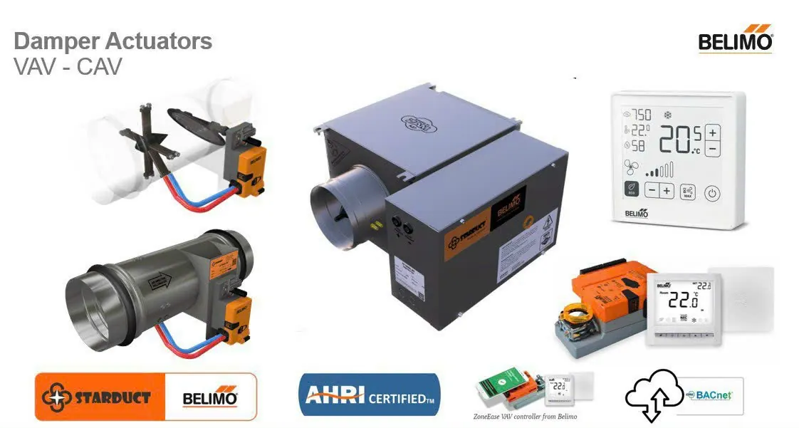
Installation & Commissioning Procedure
Proper installation is crucial to ensure the VAV system performs as designed. Key steps include:
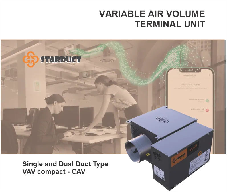
Mechanical Installation
- Mount and secure VAV boxes to the ceiling, ensuring airflow direction matches the sensor orientation (usually marked with an arrow).
- Connect inlet and outlet ducts, insulate if needed, and install flexible connectors to reduce vibration and noise.
- Install room temperature sensors in representative locations (avoid doors, windows, or vents).
- Connect pressure sensor tubing (if using remote-mounted sensors) and ensure no leaks.
- For reheat boxes, connect hot water pipes or electric heating wires correctly.
- Ensure all valves and dampers operate smoothly.
⚡ Electrical & Control Wiring
- Connect 24 VAC or 220 VAC power to actuators and controllers.
- Wire temperature and airflow sensors to the controller.
- Set up communication networks (RS485 or TCP/IP) between VAV controllers and the central control panel.
- Assign unique addresses/IDs to each VAV box to avoid conflicts.
- Perform insulation and continuity checks for electrical safety.
💻 Controller Programming & Configuration
- Load the VAV control application into DDC controllers.
- Configure parameters: network address, sensor-zone mapping, min/max airflow limits.
- Calibrate I/O settings using DDC software and commission each VAV box:
- Check damper travel range.
- Verify temperature sensor accuracy.
- Zero differential pressure sensors if needed (especially if installed at different altitudes).
🌬️ Air Balancing
- Measure actual airflow at diffusers using a balometer at max, min, and intermediate damper positions.
- Calibrate airflow sensors to match measured values.
- Ensure each VAV box delivers airflow within ±5% of design values.
- Adjust AHU fan pressure: open all VAVs, measure pressure at the farthest point, and tune VFD speed accordingly.
- Test automatic pressure control by closing some VAVs and observing system response.
🧪 Testing & Commissioning
- Run the system under peak and low-load conditions to verify control stability.
- Simulate room heating to check VAV response and airflow increase.
- Test interlocks:
- If AHU fan stops, VAV dampers should fail open.
- If fire alarm triggers, VAVs should open 100% for smoke extraction.
- Test reheat function: simulate winter, verify hot water valve opens when airflow is at minimum but room is still cold.
- Record final calibration values and generate a commissioning report.
⚠️ Important: Clean ductwork before operation to prevent dust from jamming dampers. Ensure all AHU filters are installed to protect fans and sensors.
🧰 Common Issues and Troubleshooting
🔧 Sensor Failures
- Faulty or drifted temperature sensors can cause overcooling or overheating.
- Dirty or miscalibrated airflow sensors may misreport flow, leading to incorrect damper positions.
- Solution: recalibrate sensors regularly (every 6–12 months).
⚙️ Stuck Dampers or Actuator Failures
- Dust or mechanical wear may cause dampers to stick or actuators to fail.
- Symptoms: room temperature doesn’t change despite control signals.
- Some actuators fail-safe to 100% open, causing overcooling.
- Solution: inspect and replace actuators as needed.
💨 Airflow Imbalance
- “Starved box” issue: distant VAVs receive insufficient pressure, even at full open.
- Nearby boxes may receive excess pressure, causing noise.
- Solution: rebalance system, adjust duct dampers, or increase fan setpoint if capacity allows.
🖥️ Control/BMS Errors
- Communication loss or software bugs can disrupt operation.
- Example: VAV reverts to standalone mode, losing optimization features.
- Solution: check BMS logs and control logic.
💧 Condensation or High Humidity
- Too low supply air temperature or too little airflow can cause condensation at diffusers.
- Solution: set minimum supply air temperature (~13°C) and airflow limits.
🔊 Noise Issues
- High inlet pressure causes whistling when dampers close too much.
- Solution: reduce system pressure or install silencers.
- Fan-powered VAVs may produce noise if bearings wear out.
🧠 Expert Insight: After a decade, rubber and plastic parts degrade, sensors drift, actuators stick, and heating valves may leak—leading to poor temperature control and wasted energy.
🛡️ Periodic Maintenance
🌀 AHU & Chiller
- Replace AHU filters every 3–6 months.
- Clean cooling coils, check chilled water pumps, and inspect for condensation.
- Maintain chillers annually (check refrigerant, oil, clean condenser).
📦 VAV Box
- Check room temperature sensors with a reference thermometer.
- Verify airflow sensor accuracy using pressure taps.
- Clean inside the box, especially dampers and sensors.
- For fan-powered VAVs: lubricate or replace bearings if noisy.
- Test actuators manually for smooth operation.
- Inspect reheat valves: bleed air, check for leaks or stuck valves.
🧠 Control System
- Check controller backup batteries.
- Regularly back up BMS programs and databases.
- Update firmware as recommended.
📊 Tip: Use BMS trending to detect anomalies—e.g., rooms with large temperature swings or excessive reheat usage.
🧼 Duct & Diffuser Cleaning
- Clean every 3–5 years to maintain air quality and sensor accuracy.
👨🏫 Operator Training
- Train staff to recognize BMS alarms, understand system diagrams, and manually operate valves during failures.
- Keep maintenance logs and manuals up to date.