
Tunnel damper
High-airflow dampers for tunnel, station and basement ventilation and smoke extraction — made to each project's sizes and requirements.
Added to your quotation request list. Open the quotation request list →
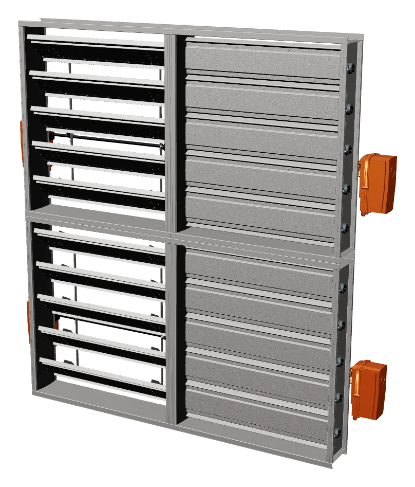
Module assembly (wide × high), code STD-TD-<W>x<H>
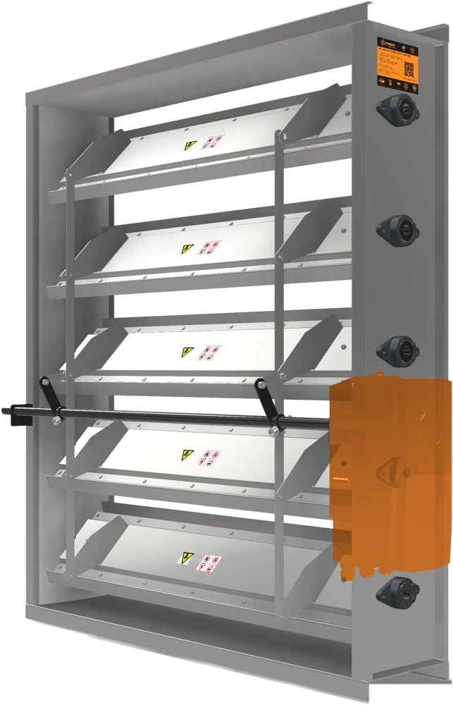
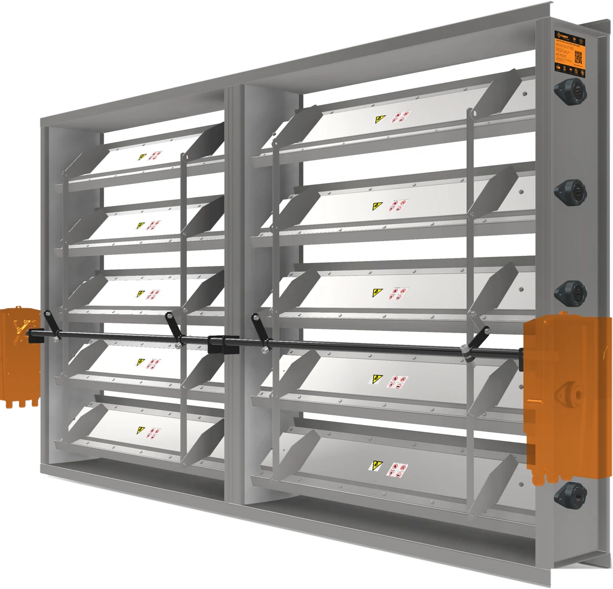
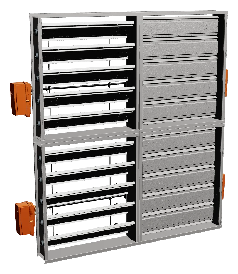
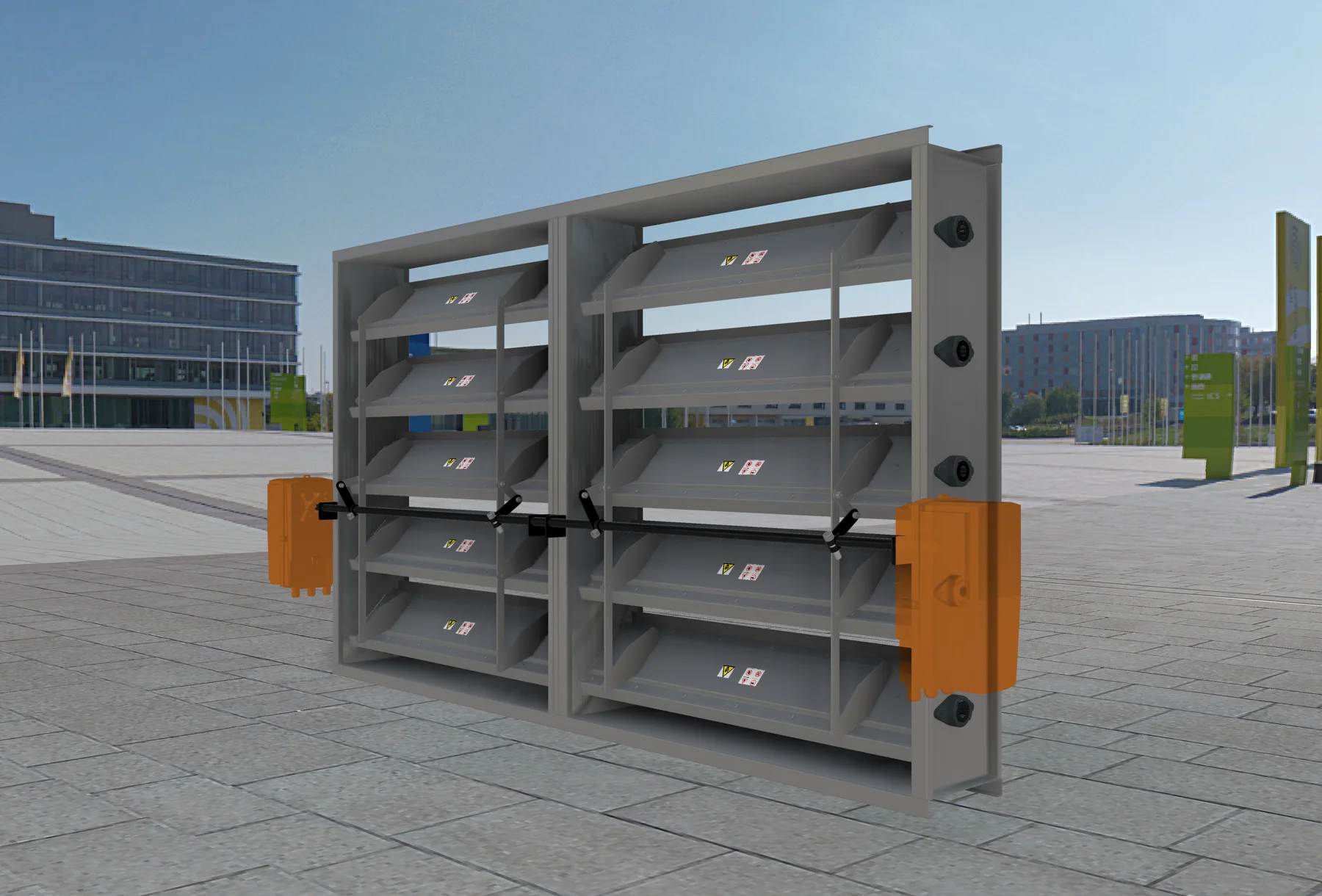
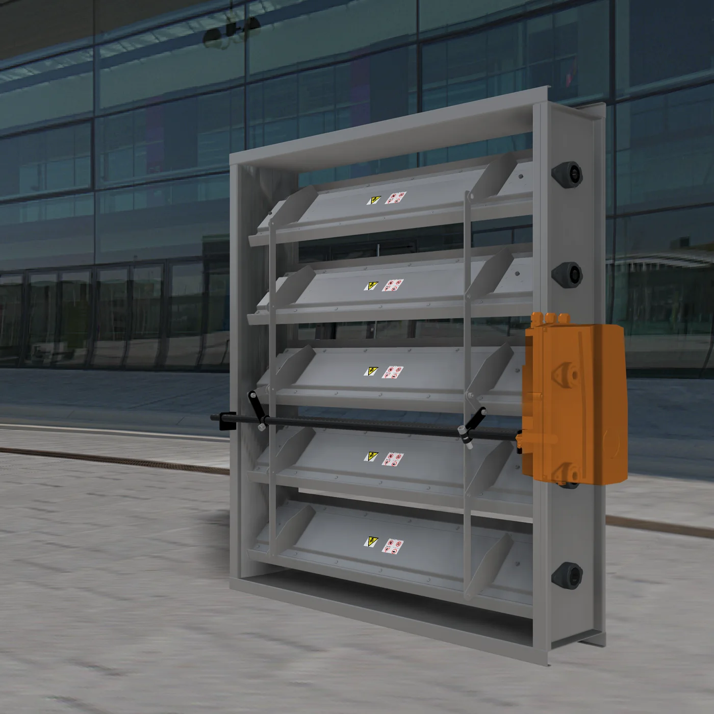
Rendered from the 3D model; actual configuration per project documents.
Description
Tunnel dampers open / close, modulate and isolate the air paths of ventilation and smoke-extraction systems in road and rail tunnels, metro stations, basements and other large spaces that need very high airflow at high pressure. In a fire, the damper must operate in a stream of hot smoke.
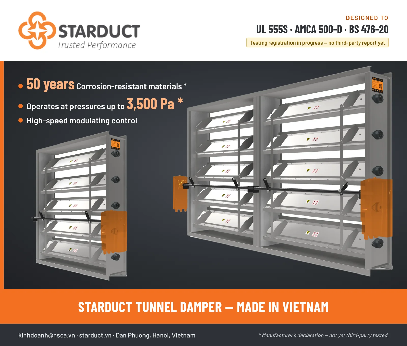
Starduct designs and manufactures the dampers project by project: size, number of modules, actuation and heat-resistance requirement follow the design documents. The dampers are designed to UL 555S / AMCA 500-D / BS 476-20 and testing registration is in progress; there is no third-party test report yet, so this page gives only two manufacturer-declared figures (working pressure, material durability), marked as not third-party tested.
Applications
- Tunnel ventilation with jet fans / axial fans
- Smoke extraction and pressurisation in stations, basements and underground malls
- Isolating air paths and preventing backflow when fans stop
- Intake / discharge openings of ventilation stations
Typical construction — configured per project
- Reinforced steel frame, steel airfoil blades; large openings built from several modules
- Standard 1 m × 1 m module with one actuator per module; any number of modules can be combined — 4 × 4 m assemblies are common
- Standard frame and blade material: zinc–aluminium–magnesium (ZAM) coated steel; SUS304 / SUS316 stainless optional; 2.0 mm sheet
- High-temperature silicone blade seals (stainless optional); stainless-steel jamb seals
- Shafts and bearings selected for the required operating temperature
- Electric or pneumatic actuation; fail-safe position as designed
- Limit switches for status; materials and coating to suit the environment
- High-pressure circular damper option for supply / exhaust systems
Manufacturer's declared data
- Maximum working pressure: 3,500 Pa
- Corrosion-resistant materials, 50-year durability
Manufacturer's declaration — not yet third-party tested.
Standards and testing status
- Designed to UL 555S (heat and smoke leakage), BS 476-20 (fire resistance) and AMCA 500-D (aerodynamics) — testing registration in progress.
- No third-party test report yet: pressure drop, leakage and heat resistance of each configuration are provided by Starduct with the quotation and identified as calculated.
General selection guide
- Clear size W × H to match the design duct / opening; large sizes are built from several modules.
- Check the face velocity at the design airflow — the tool below calculates area, velocity and velocity pressure for reference.
- State in the quotation request: heat resistance (temperature / duration), closed leakage, working pressure, actuation, control voltage, feedback signals and fire-system interlocks.
Send the size, airflow, heat-resistance requirement and actuation — Starduct sales will advise the configuration and quote.