Your cart0 Products
There are no products yet
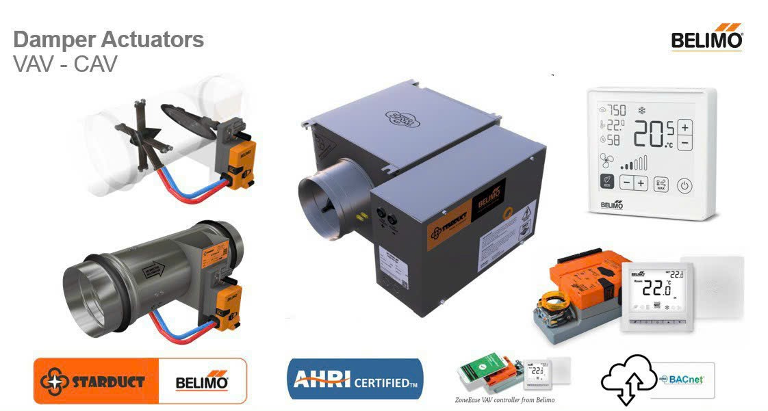
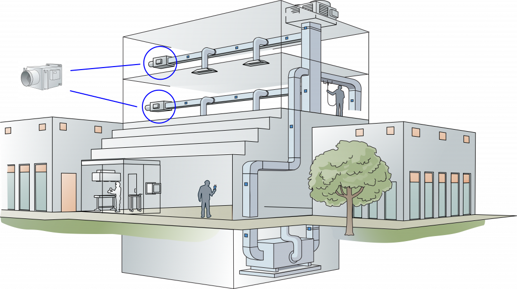
Designing an effective Variable Air Volume (VAV) system requires a harmonious approach from the central plant to each zone. The core components include a central Air Handling Unit (AHU), zone-specific VAV terminal units, distribution ductwork, and a responsive control system.
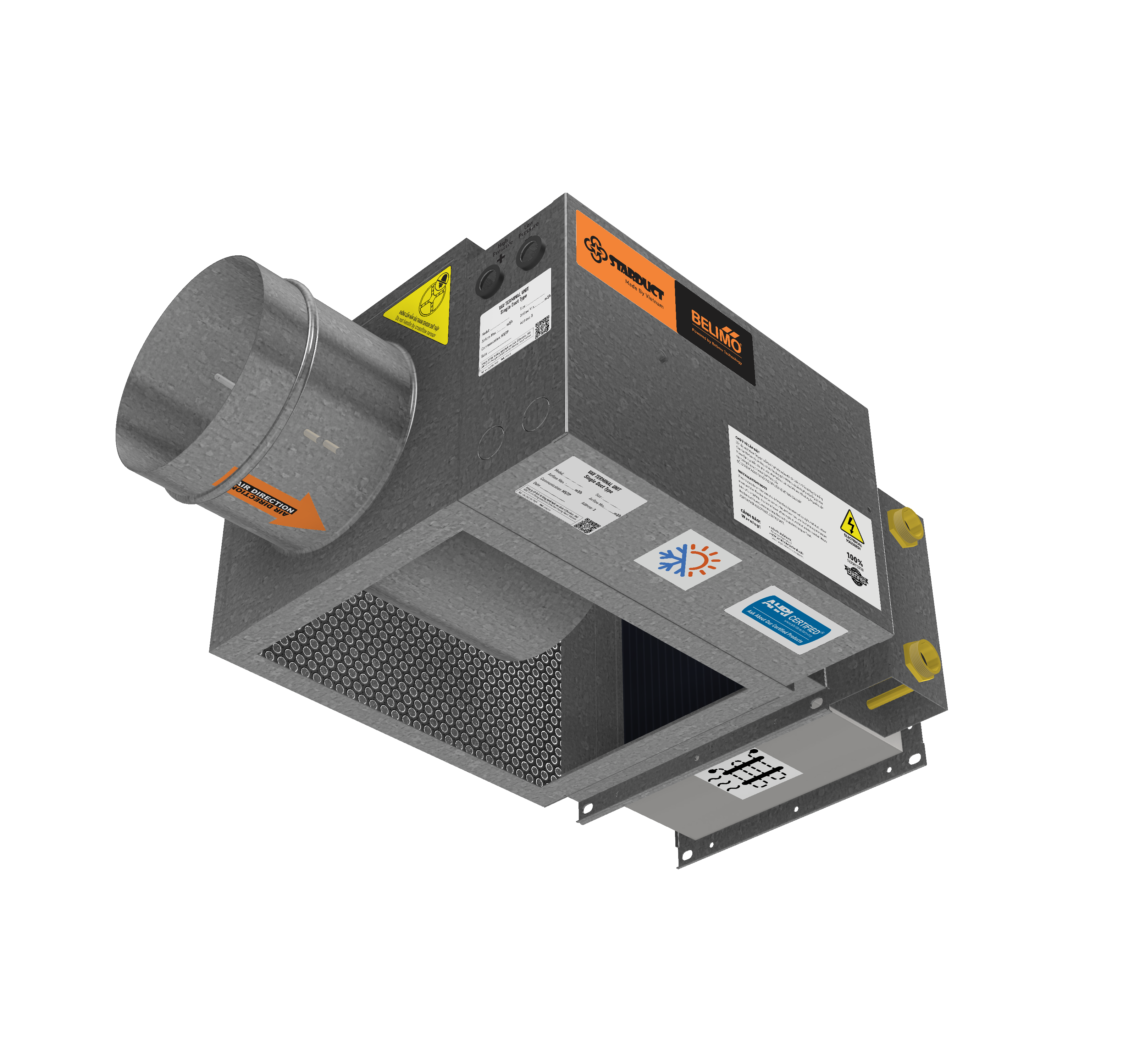
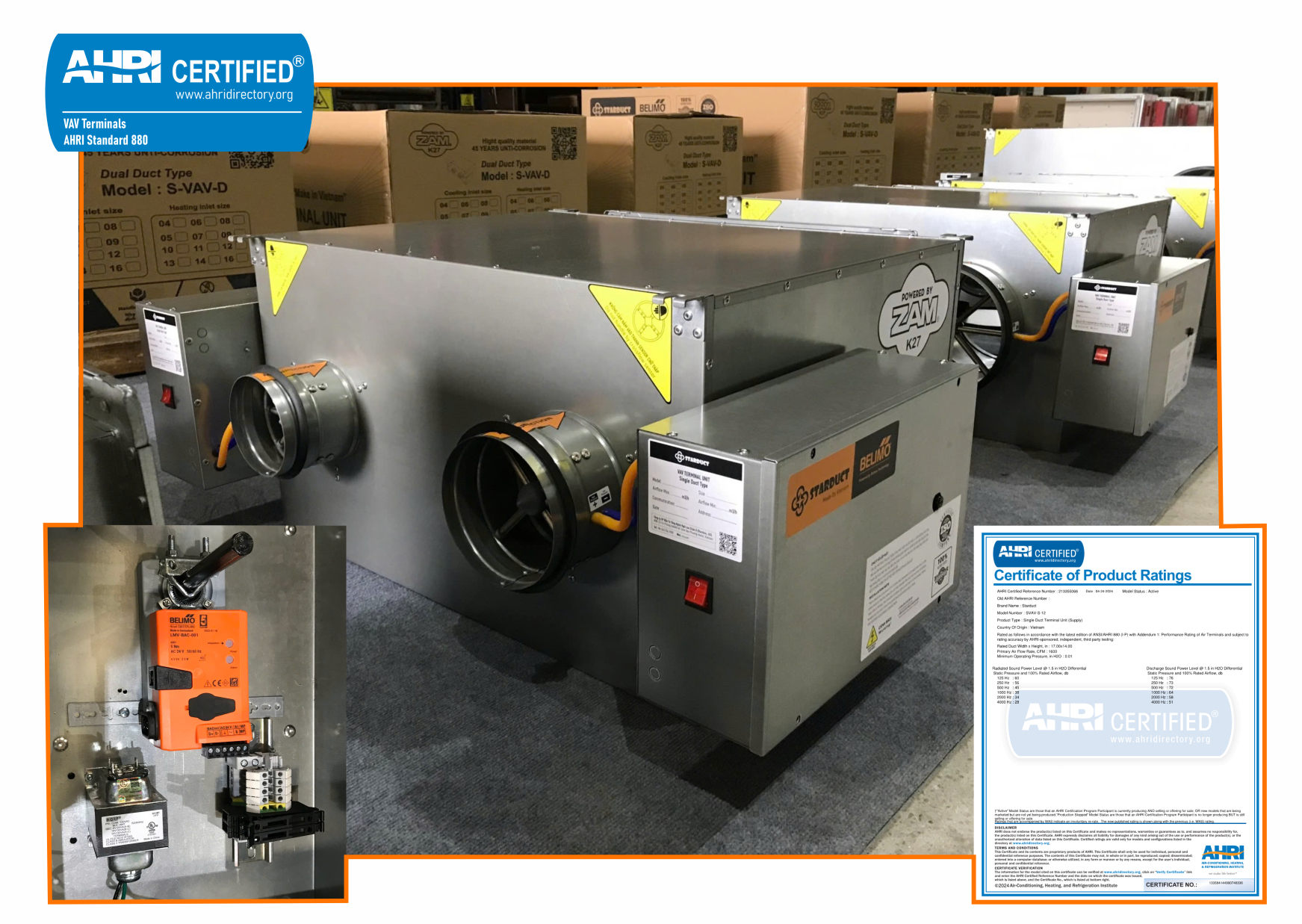
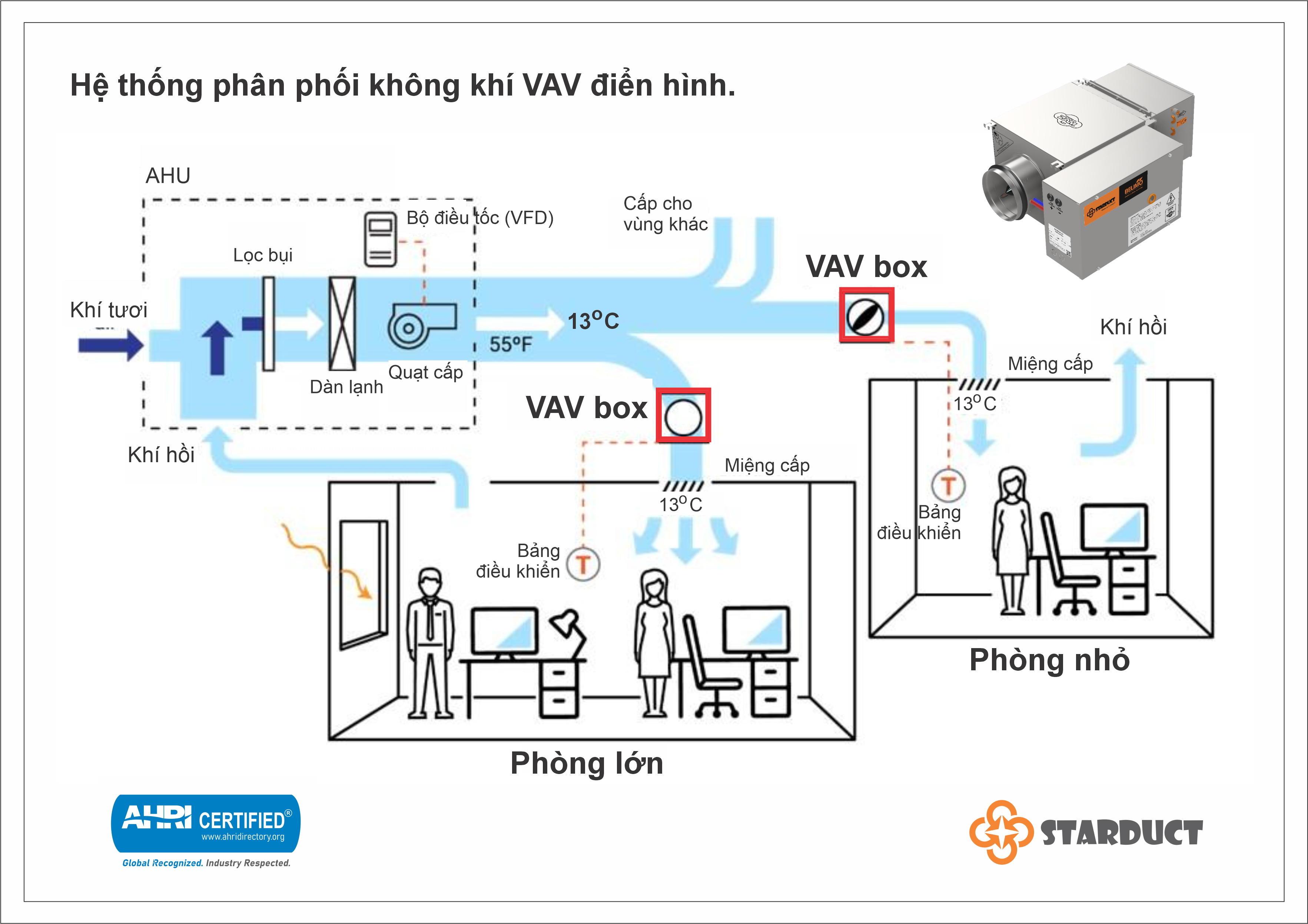
In a typical setup, the central AHU supplies conditioned air at approximately 12°C through the main duct. Each VAV box—assigned per zone—modulates airflow via a damper to match the room’s thermal demand. Many boxes include airflow sensors and built-in controllers to ensure minimum ventilation is maintained, even during low load periods, avoiding complete shutoff of fresh air.
Modern AHUs typically integrate Variable Frequency Drives (VFDs) for supply fans. These adjust fan speed based on system demand, significantly reducing energy use. A static pressure reset algorithm dynamically controls the fan to maintain pressure just sufficient for the “critical” (farthest open) VAV box. As more zones close their dampers, fan speed decreases to avoid excessive pressure—and wasted energy.
Additionally, supply-air temperature reset is used: when system-wide cooling demand drops, the AHU increases supply air temperature (e.g., from 12°C to 14–15°C), reducing chiller load and minimizing reheating needs at perimeter zones

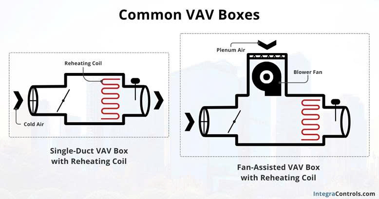
Figure 1: Schematic of a typical HVAC system using VAV air distribution (AHU supplies cooled air into ductwork, which passes through VAV boxes to serve various zones). Each VAV box modulates airflow via a damper controlled by a zone-level DDC controller based on room temperature..
Effective zone design is key to a successful VAV system. The fundamental principle: each zone should have its own dedicated VAV box, allowing independent control based on that zone's specific thermal load. Zones are typically defined by areas with similar load characteristics and occupancy schedules—such as large rooms, clusters of west-facing offices, or densely occupied halls.
Engineers must calculate:
VAV boxes should be positioned:
| Aspect | Design Guidance |
|---|---|
| Duct Sizing | Use adequately sized ducts to limit pressure drop, while avoiding oversized ducts that consume space and inflate cost. Suggested air velocities: 5–7 m/s (main duct), 3–5 m/s (branches). |
| VAV Box Placement | Locate near zones for responsive feedback; avoid long ducts that delay control. Allow access for maintenance (sensor replacement, damper servicing). |
| System Configuration | Match zoning with space usage. For small offices, divide into smaller zones to minimize airflow when unoccupied. Open areas may need wide coverage with multiple sensors to avoid thermal imbalance. |
| Future Flexibility | Design for adaptability—additional VAVs can be added if AHU capacity and controls permit. Leave room on ductwork for future expansion. |
To optimize performance, a VAV system should be fully integrated across central cooling/heating and zone control levels:
Each AHU and VAV terminal is equipped with a Direct Digital Controller (DDC) connected to the building network. Functions include:
The BMS supervisory software manages higher-level control such as:
BAS enables advanced strategies:
This architecture allows real-time coordination between AHU and VAVs, maximizing comfort and energy savings.
In short: "Both the AHU and VAV boxes are equipped with DDCs and interconnected via the BAS. System monitoring and adjustments are typically performed centrally via the BMS interface, allowing remote management and performance optimization."